In the world where technology is evolving rapidly, computers and its uses grew rapidly and widely through out the world helping to resolve most simple problems (like steaming videos) to complex problems (like performing most complex calculations) human life encounters in daily life.
But have we wondered how does a computer works? What is the fundamentals block diagram of computer? Just like the other machines, the computer has also a basic architecture.
Five basic operations performed by computer are:
- Input
- Output
- Storing
- Processing
- Controlling
In this article we will understand basic block diagram of computer and also see how does each part works and functionalities associated with it.
Block Diagram Of Computer
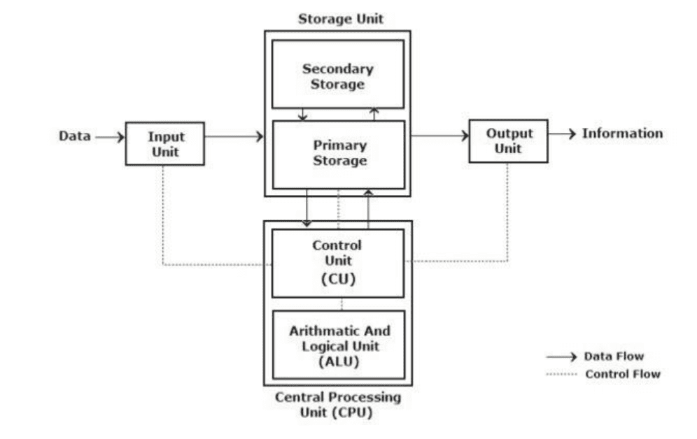
Input Unit
Input Unit is an essential part of block diagram of computer that provides computer with data and instruction for solving problem. It consists of one or more input devices that provide instructions/data into computers. Major functionalities associated with this unit are:
- Accept the data and instructions from the outside world into computers
- Converting it to a form/type that the computer can understand.
- Supply the converted data to the computer system for further processing.
Some of the input devices are:
| Keyboard | Graphic Tablet |
| Mouse | Microphone |
| Magnetic Ink Card Reader(MICR) | Joy Stick |
| Light pen | Optical Character Reader(OCR) |
| Bar Code Reader | Track Ball |
| Scanner | Optical Mark Reader(OMR) |
Storage Unit
This unit of block diagram of computer stores data and instructions provided by the input unit before processing. It also holds intermediate and final processed data which can be sent to output devices. Main functionality includes
- Holding data and instructions provided by input devices for processing
- Storing intermediate results of processing for further use.
- Providing stored data to output devices to be seen by user.
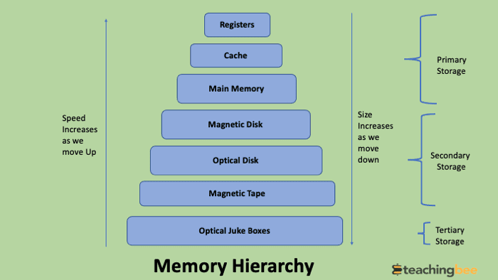
The storage unit is divided into three major types:
- Primary Storage: This type of memory is directly accessible by processing unit and provides data very fast. This type of storage is volatile which means data is lost, when the computer is switched off or rebooted In order to store the data permanently, the data has to be transferred to the secondary memory. RAM, cache memory etc. are some of the examples of this.
- Secondary Storage: Secondary storage is used like an archive and is not directly accessible to processing unit directly. This type of storage is persistent and non volatile, meaning data is not lost as long as it is removed by external factors. Floppy Disks, USB drives are some the examples of it.
- Tertiary Memory: This type of storage is not seen in personal computers and involves a robotic mechanism for mounting and dismounting removable mass storage media into a storage device according to the system’s demands. Mainly it is used to archive or store very rarely used information as retrieving information from these devices is very slow.Typical examples include tape libraries and optical jukeboxes.
Data Storage Units
All digital computers use the binary system, i.e. 0’s and 1’s. Each character or a number is represented by an 8-bit code. The set of 8 bits is called a byte.
| Unit | Abbrevation | Capacity | Powers Of 2 |
|---|---|---|---|
| Bit | b | 1 | 20 |
| Byte | B | 8 bits | 23 |
| Kilobyte | KB | 1024 bytes | 210 |
| Megabyte | MB | 1024 kilobytes | 220 |
| Gigabyte | GB | 1024 megabytes | 230 |
| Terabyte | TB | 1024 gigabytes | 240 |
| Petabyte | PB | 1024 terabytes | 250 |
| Exabyte | EB | 1024 petabytes | 260 |
| Zettabyte | ZB | 1024 exabytes | 270 |
| Yottabyte | YB | 1024 zettabytes | 280 |
Central Processing Unit
The Central processing unit or the CPU is the brain in block diagram of computer. It has following functionalities:
• Its ALU unit performs all calculations.
• It takes all decisions.
• ControlUnit helps to control all units of the computer.
CPU majorly consists of two components
- Arithmetic Logical Unit
- Control Unit
Arithmetic Logical Unit
An arithmetic logic unit (ALU) is a digital circuit used to perform arithmetic and logic operations. It represents the fundamental building block of the central processing unit (CPU) of block diagram of computer. All calculations are performed in the Arithmetic Logic Unit (ALU) of the computer. The ALU can perform basic operations such as addition, subtraction, multiplication, division, etc and does logic operations.
All the calculations are performed by this unit. The control unit sends essential data from storage unit to ALU and once calculations and computation is done, the results are again stored back to storage unit by control unit, further which is transferred to output unit.
Control Unit
This unit controls all other units in the computer like instructing the input unit, where to
store the data after receiving it from the outside. It is also responsible for controlling the flow of data and instructions from the storage unit to ALU and vice versa as discussed above.
The control unit can be seen as central nervous system of block diagram of computer.
Output Unit
All the information sent to the computer once processed is received by the user through the output unit. This part of block diagram of computer provides the desired result to the user. Some of the output devices are:
| Monitor | Printer |
| Headphones | Computer Speakers |
| GPS | Projector |
| Speech-Generating Device | Video Card |
| Braille Reader | Sound Card |
Conclusion
In Summary, data and instructions from outside world is accepted by input unit. The computation and decision making is handled by processing unit which includes ALU and control unit which is stored in storage unit that can be temporary or permanent and provided to user by output unit. This was all about block diagram of computer.
Got a question or just want to chat? Comment below or drop by our forums, where a bunch of the friendliest people you’ll ever run into will be happy to help you out!