Table of Contents
ToggleOne of the major problem with the adders is that they produce carry propagation delay while doing arithmetic operations like multiplication, division etc which involves many addition and subtraction steps. which makes these adders very slow. Thus reducing the carry propagation delay of adders will enhance the speed of these adders.
Here’s when carry look ahead adder comes into picture. It is a type of adder which helps in improving the speed by calculating one or more carry bits before the sum, thus reducing the time required to determine the carry bits. The carry look ahead adder reduces the wait time which is required to calculate the result of very large value bits, thus reducing carry propagation delay.
Carry Look Ahead Adder
The carry look ahead adder works as follows:
- A carry signal will always be generated in two cases:
- When both bits Ai and Bi are 1, or
- When one of the two bits is 1 and the carry-in (carry of the previous stage) is 1.
- For each digit position, carry look ahead adder calculates whether that position is going to propagate a carry if one comes in from the right.
- Then it combines the calculated values to deduce quickly whether, for each group of digits, that group is going to propagate a carry that comes in from the right.
- They work by creating two signals P and G known to be Carry Propagator and Carry Generator.
- The carry propagator is propagated to the next level whereas the carry generator is used to generate the output carry regardless of input carry.
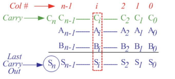
Let’s understand this with example. Consider the case of adding two n-bit numbers A and B.


The below full adder adds operands in ith column Ai, Bi and carry bit Ci. The output sum and carry is dependent on the two signals carry propagator(P) and carry generator(G) whose values are as follows


Pi = Ai ⊕ Bi
Gi = AiBi
Thus, sum and carry equations can be represented in terms of P and G as follows, where Ci+1 is look ahead carry.
Si = Pi ⊕ Ci
Ci +1 = Gi + PiCi
- Gi is known as the Carry Generator signal since a carry (Ci+1) is generated whenever Gi = 1, regardless of the input carry (Ci).
- Pi is known as the Carry Propagator signal since whenever Pi =1, the input carry is propagated to the output carry, i.e., Ci+1. = Ci (note that whenever Pi =1, Gi =0).
Note: The values of propagator and generator signals is only dependant on the input operand bits i.e (Ai & Bi).
These signals settle to their steady-state value after the propagation through their respective gates and computed values of all the Pi’s are valid one XOR-gate delay after the operands A and B are made valid. Also, computed values of all the Gi’s are valid one AND-gate delay after the operands A and B are made valid.
Expressions
The Boolean expression of the carry outputs of various stages can be written as follows:
C1 = G0 + P0C0
C2 = G1 + P1C1 = G1 + P1 (G0 + P0C0) = G1 + P1G0 + P1P0C0
C3 = G2 + P2C2 = G2 + P2G1 + P2P1G0 + P2P1P0C0
C4 = G3 + P3C3 = G3 + P3G2 + P3P2G1 + P3P2P1G0 + P3P2P1P0C0
To Generalise, the carry outputs for each stage are functions of Ci = Fi(P’s, G’s , C0). Here, we can see that each carry signal is expressed as a direct SOP function of C0 rather than its preceding carry signal
Carry Look Ahead Adder Circuit Diagram
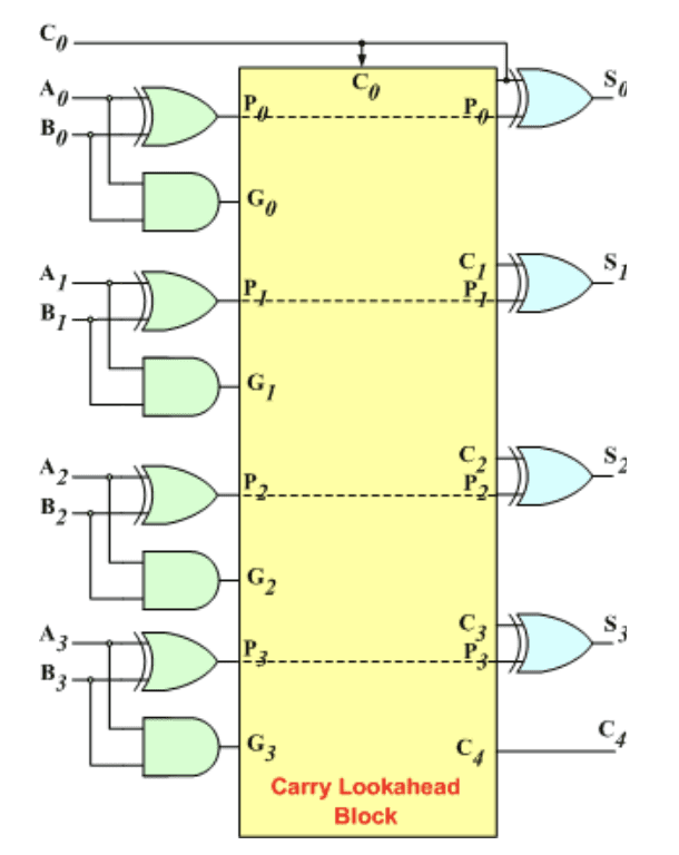
The 4-bit carry look-ahead (CLA) adder consists of 3 levels of logic. The below circuit diagram shows the same.


- First level: All the P & G signals are generated in this level. Output signals of this level (P’s & G’s) will be valid after 1τ.
- Second level: The Carry Look-Ahead (CLA) logic block which consists of four 2-level implementation logic circuits. It generates the carry signals (C1, C2, C3, and C4) as defined by the above expressions. Output signals of this level (C1, C2, C3, and C4) will be valid after 3τ.
- Third level: The sum signals (Si = Pi ⊕ Ci) is generated by four XOR gates. Output signals of this level (S0, S1, S2, and S3) will be valid after 4τ.
Thus, the 4 Sum signals will all be valid after a total delay of 4τ in carry look ahead adder compared to a delay of (2n+1)τ for Ripple Carry adders, for 4-bit ripple adder (n = 4), the delay is 9τ.
Advantage
- The carry propagation delay is reduced.
- It provides the fastest addition logic.
Disadvantage
- The disadvantage of the CLA adders is that the carry expressions (and hence logic) become quite complex for more than 4 bits.
- The circuit is costlier as it involves more number of hardware.
Conclusion
Carry propagation delay of adders is major problem in ripple adders which is major cause of slow speed for arithmetic computation. Carry Look ahead adders tries to solve this problem by calculating carry bits before sum using Carry Generator and Carry Propagator. This was all about carry look ahead adder. Checkout other related article to know difference between half and full adder.
Got a question or just want to chat? Drop by our forums, where a bunch of the friendliest people you’ll ever run into will be happy to help you out!


